Creating HA Juniper SRX Chassis Cluster
Table of Contents
This guide is for a clean clustering of 2 Juniper SRX Series firewalls
Topology⌗
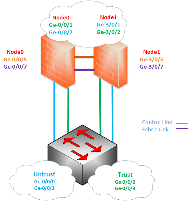
The topology that will be used, in the series of new posts, based on configuring, failing over and upgrading a High Availability (HA) Juniper SRX Chassis Cluster. The hardware used were: 2x Juniper SRX220H2 (brand new with factory-default settings) and 1x Juniper EX4200. As I’m using a single EX4200, I configured two routing-instances “Trust” and “Untrust”. By using the routing-instances’ I’m able to have multiple routing-tables on a single device without creating routing loops. The tabs below will provide diagrams of the physical, logical and the full configuration on EX4200.
Physical Topology⌗
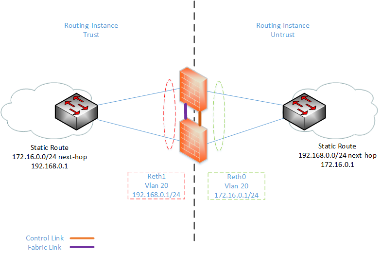
Logical Topology⌗
EX4200 Configuration⌗
set interfaces ge-0/0/0 description "SRX220 Bottom untrust interface"
set interfaces ge-0/0/0 enable
set interfaces ge-0/0/0 unit 0 family ethernet-switching port-mode trunk
set interfaces ge-0/0/0 unit 0 family ethernet-switching vlan members untrust

set interfaces ge-0/0/1 description "SRX220 Top untrust interface"
set interfaces ge-0/0/1 enable
set interfaces ge-0/0/1 unit 0 family ethernet-switching port-mode trunk
set interfaces ge-0/0/1 unit 0 family ethernet-switching vlan members untrust

set interfaces ge-0/0/2 description "SRX220 Bottom trust interface"
set interfaces ge-0/0/2 enable
set interfaces ge-0/0/2 unit 0 family ethernet-switching port-mode trunk
set interfaces ge-0/0/2 unit 0 family ethernet-switching vlan members trust

set interfaces ge-0/0/3 description "SRX220 Top trust interface"
set interfaces ge-0/0/3 enable
set interfaces ge-0/0/3 unit 0 family ethernet-switching port-mode trunk
set interfaces ge-0/0/3 unit 0 family ethernet-switching vlan members trust

set interfaces vlan unit 10 description untrust
set interfaces vlan unit 10 family inet address 172.16.0.2/24

set interfaces vlan unit 20 description trust
set interfaces vlan unit 20 family inet address 192.168.0.2/24

set routing-instances trust instance-type virtual-router
set routing-instances trust interface vlan.20
set routing-instances trust routing-options static route 172.16.0.0/24 next-hop 192.168.0.1

set routing-instances untrust instance-type virtual-router
set routing-instances untrust interface vlan.10
set routing-instances untrust routing-options static route 192.168.0.0/24 next-hop 172.16.0.1

set vlans trust vlan-id 20
set vlans trust l3-interface vlan.20

set vlans untrust vlan-id 10
set vlans untrust l3-interface vlan.10
Some of the pre-checks that will need to be done before you start:
Chassis Cluster⌗
Remove chassis cluster. (You don’t need to this brand new firewalls but I just to do, better to save that sorry) This is done from operational mode and will reboot the device.
set chassis cluster disable reboot
Hardware⌗
Check that you are using the same hardware as you can’t have mixed chassis clustered firewalls
root@lab_SRX220_Bottom> show chassis hardware
Hardware inventory:
Item             Version  Part number  Serial number     Description
Chassis                                CF4713AK0219      SRX220H2
Routing Engine   REV 04   750-048778   ACKS2263          RE-SRX220H2
FPC 0                                                    FPC
  PIC 0                                                  8x GE Base PIC
Power Supply 0
Junos Version⌗
Check that you have the same code version of Junos
root@lab_SRX220_Bottom> show version
Hostname: lab_SRX220_Bottom
Model: srx220h2
JUNOS Software Release [12.1X44-D40.2]
Once you have confirmed that the hardware and software versions are the same you can start with the chassis cluster
Having confirmed that both SRX220’s identical starting configuration, we can begin the clustering:
Physically connect the 2 devices together to Create the control and fabric (data) links. Nodes in cluster use these links to communicate between each other about the cluster health, status and other traffic information. Control link is used to configure the nodes in the cluster and the Data link allows session synchronization between nodes. The Control and Fabric interfaces are hardware specific, so different models have will use different ports. You can see each specific model’s control and fabric ports via the Juniper Knowledge Centre
On the SRX220H for the Control link:
You will need to connect ge-0/0/7 on SRX A (node 0) to ge-0/0/7 on SRX B (node1). This will change to ge-3/0/7 once the chassis cluster has been completed
On the SRX220H for the Fabric Link
You will need to connect ge-0/0/5 on node 0 to ge-0/0/5 on node 1. As with the control link, this interface will change to ge-3/0/5 once the chassis cluster has been completed
Next, we need to cluster mode. As with removing the chassis cluster configuration from before, this will reboot the firewalls and will need to done from operational mode.
set chassis cluster cluster-id 1 node 0 reboot
set chassis cluster cluster-id 1 node 1 reboot
- The cluster ID on the firewalls will need to be the same, however the node ID has to be different. This is numbered between 0 and 1
- The command above has been done on both devices
- Although you are given the option to pick a cluster ID from 0-15, using ID 0 is the same as disabling the cluster mode. You will need to pick a number between 1-15, this has to do with how virtual MACs are calculated
We can verify that chassis cluster was successful by running
root@lab_SRX220_Top> show chassis cluster status
Cluster ID: 1
Node                  Priority          Status    Preempt  Manual failover

Redundancy group: 0 , Failover count: 1
    node0                   1           primary        no       no
    node1                   1           secondary      no       no
Now that we have the chassis cluster completed, we can start with the configuration. We can do the entire configuration on the primary node0 and anything that is committed on the primary node0 will be copied onto the secondary node1
We sent the management interfaces (fxp0) on each of the nodes. This will allow us to have remote SSH access onto each node.
set groups node0 system host-name SRXA
set groups node0 interfaces fxp0 unit 0 family inet address 10.1.0.201/24
set groups node1 system host-name SRXB
set groups node1 interfaces fxp0 unit 0 family inet address 10.1.0.202/24
set apply-groups "${node}"
Adding the command
set apply-groups "${node}"is mandatory, as it ensures that the node specific configuration is only committed on that specific node
Now, its time to configure the Fabric links in the cluster
set interfaces fab0 fabric-options member-interfaces ge-0/0/5
set interfaces fab1 fabric-options member-interfaces ge-3/0/5
We can check the interfaces, we have just committed
root@lab_SRX220_Top# run show chassis cluster interfaces
Control link status: Up

Control interfaces:
    Index   Interface        Status
    0       fxp1             Up

Fabric link status: Up

Fabric interfaces:
    Name    Child-interface    Status
                               (Physical/Monitored)
    fab0    ge-0/0/5           Up   / Up
    fab0
    fab1    ge-3/0/5           Up   / Up
    fab1
Configure the Redundancy Groups 0 and 1. The purpose of the redundancy groups is that in a failure situation the control panel (Routing-Engine) can be failed over to the secondary node. In a HA Cluster, Redundancy group 0, by default, represents the control plane. The node that is the master of Redundancy Group 0 (in this example node0) will be the Active Routing-Engine (RE). The Active RE is master of the Cluster; it is responsible for pushing any new configuration changes and controlling the data plane. Any changes that need to be done in the cluster will have to be done via the Active RE. If node0 was to failover, Node1 will be the new Active RE, although you can only have one Active RE node, a single node can be the primary node for a number redundancy groups. By setting the priority higher on node0, ensures that the node0 is the master of both redundancy groups. By using Preempt on the redundancy group 1 means that if node0 fail and a failover to node1 occured, once node0 became active it will automatically take ownership of the chassis cluster and become the Active RE again.
set chassis cluster redundancy-group 0 node 0 priority 100
set chassis cluster redundancy-group 0 node 1 priority 1
set chassis cluster redundancy-group 1 node 0 priority 100
set chassis cluster redundancy-group 1 node 1 priority 1
set chassis cluster redundancy-group 1 preempt
Next, step will be to configure interface monitoring. This will check the health and physical status of the each of the interfaces. Interface monitoring can be used to trigger a failover in the event link status on an interface goes down. By default interface monitoring has a threshold of 255, once this number is reached the redundancy group priority will be changed to ‘0’ for the specific node. If one or more interfaces monitored fail the redundancy group will fail over to other node.
set chassis cluster redundancy-group 1 interface-monitor ge-0/0/1 weight 255
set chassis cluster redundancy-group 1 interface-monitor ge-3/0/1 weight 255
set chassis cluster redundancy-group 1 interface-monitor ge-0/0/2 weight 255
set chassis cluster redundancy-group 1 interface-monitor ge-3/0/2 weight 255
Setting the interfaces. With SRX you need set Redundancy Ethernet (Reth) count before you are able to assign physical interfaces. The Reth interface is a logical aggregated interface that allows port bundling between the nodes. For this example, I only will only need 2 reth0 (1 for the trust and 1 for untrust). Once the reth number has been applied, you will be able to assign the physical interfaces.
set chassis cluster reth-count 2
set interfaces ge-0/0/1 gigether-options redundant-parent reth1
set interfaces ge-3/0/1 gigether-options redundant-parent reth1
set interfaces ge-0/0/2 gigether-options redundant-parent reth0
set interfaces ge-3/0/2 gigether-options redundant-parent reth0
It’s recommended that you only provision reth interfaces, as you need them. This is so you conserve resources on the firewall
Similarly with Aggregated Ethernet interfaces on EX or MX Series, you will do the entire configuration for the reth under the logical interface. You need to define the interfaces redundancy group. As redundancy group 0 is control panel for this example both reth interfaces will be in redundancy group 1.
set interfaces reth0 vlan-tagging
set interfaces reth0 redundant-ether-options redundancy-group 1
set interfaces reth0 unit 10 description Untrust
set interfaces reth0 unit 10 vlan-id 10
set interfaces reth0 unit 10 family inet address 172.16.0.1/24

set interfaces reth1 vlan-tagging
set interfaces reth1 redundant-ether-options redundancy-group 1
set interfaces reth1 unit 20 description trust
set interfaces reth1 unit 20 vlan-id 20
set interfaces reth1 unit 20 family inet address 192.168.0.1/24
For my topology, I used VLAN interfaces, vlan-tagging had to be enabled and the links downstream were trunk interfaces. I also used Routing-Instances for the trust and untrust zones, as I used the global routing table as management of the device. I have added a diagram and configuration file of testing setup
To ensure that end-to-end connectivity was as expected, I had created these security zones and security policies, to get the communication between the two reth interface. The zones and policies are very vanilla, as I just need to be able to ping across.
Zones and Policies⌗
set security policies from-zone untrust to-zone trust policy ping match source-address any
set security policies from-zone untrust to-zone trust policy ping match destination-address any
set security policies from-zone untrust to-zone trust policy ping match application junos-icmp-all
set security policies from-zone untrust to-zone trust policy ping then permit

set security policies from-zone trust to-zone untrust policy ping match source-address any
set security policies from-zone trust to-zone untrust policy ping match destination-address any
set security policies from-zone trust to-zone untrust policy ping match application junos-icmp-all
set security policies from-zone trust to-zone untrust policy ping then permit

set security zones security-zone trust tcp-rst
set security zones security-zone trust host-inbound-traffic system-services all
set security zones security-zone trust interfaces reth1.20

set security zones security-zone untrust tcp-rst
set security zones security-zone untrust host-inbound-traffic system-services all
set security zones security-zone untrust interfaces reth0.10

set routing-instances Testing instance-type virtual-router
set routing-instances Testing interface reth0.10
set routing-instances Testing interface reth1.20
From my end device, I had end-to-end reachability
root> ping 172.16.0.2 routing-instance trust
--- 172.16.0.2 ping statistics ---
31 packets transmitted, 31 packets received, 0% packet loss
round-trip min/avg/max/stddev = 1.851/1.964/2.273/0.105 ms

root> ping 192.168.0.2 routing-instance untrust
--- 192.168.0.2 ping statistics ---
30 packets transmitted, 30 packets received, 0% packet loss
round-trip min/avg/max/stddev = 1.842/1.971/2.675/0.163 ms
And from the firewall, I was able to see the pings going across as flow sessions
root@lab_SRX220_Top> show security flow session
node0:
--------------------------------------------------------------------------

Session ID: 621, Policy name: ping/5, State: Active, Timeout: 2, Valid
  In: 192.168.0.2/7 --> 172.16.0.2/6279;icmp, If: reth1.20, Pkts: 1, Bytes: 84
  Out: 172.16.0.2/6279 --> 192.168.0.2/7;icmp, If: reth0.10, Pkts: 1, Bytes: 84

Session ID: 622, Policy name: ping/4, State: Active, Timeout: 2, Valid
  In: 172.16.0.2/9 --> 192.168.0.2/6277;icmp, If: reth0.10, Pkts: 1, Bytes: 84
  Out: 192.168.0.2/6277 --> 172.16.0.2/9;icmp, If: reth1.20, Pkts: 1, Bytes: 84

Session ID: 623, Policy name: ping/5, State: Active, Timeout: 2, Valid
  In: 192.168.0.2/8 --> 172.16.0.2/6279;icmp, If: reth1.20, Pkts: 1, Bytes: 84
  Out: 172.16.0.2/6279 --> 192.168.0.2/8;icmp, If: reth0.10, Pkts: 1, Bytes: 84

Session ID: 624, Policy name: ping/4, State: Active, Timeout: 2, Valid
  In: 172.16.0.2/10 --> 192.168.0.2/6277;icmp, If: reth0.10, Pkts: 1, Bytes: 84
  Out: 192.168.0.2/6277 --> 172.16.0.2/10;icmp, If: reth1.20, Pkts: 1, Bytes: 84

Session ID: 625, Policy name: ping/5, State: Active, Timeout: 4, Valid
  In: 192.168.0.2/9 --> 172.16.0.2/6279;icmp, If: reth1.20, Pkts: 1, Bytes: 84
  Out: 172.16.0.2/6279 --> 192.168.0.2/9;icmp, If: reth0.10, Pkts: 1, Bytes: 84
Total sessions: 5

node1:
--------------------------------------------------------------------------
Total sessions: 0
Having now got the cluster up and working, it was time to get to some proper failover testing! In my next post will note how that went as this post is pretty long now haha
Useful Side Notes⌗
-
Make sure there NO configuration on port ge-0/0/5 - 7, I had configured on port ge-0/0/6 as need to SCP the correct version of Junos onto both firewalls and as I read that only ge-0/0/5 and ge-0/0/7 will be used, I assumed using ge-0/0/6 would be fine… This is why you should never assume. So if you need to upgrade Junos, upgrade the firewalls then delete all configuration under the interface stanza
-
Once chassis cluster has been completed and you enter configuration mode, you will get this warning
root@lab_SRX220_Top> edit
warning: Clustering enabled; using private edit
warning: uncommitted changes will be discarded on exit
Entering configuration mode
- When doing a cluster reboot, I used the command request system reboot node all and oddly had the node0 reboot as expected however the node1 couldn’t be accessed via ssh. I tried to reboot from node0 and got this:
root@lab_SRX220_Top> request system reboot node 1
error: Could not connect to node1 : No route to host
error: Unable to send command
Doing a chassis check I saw that node1 was lost
root@lab_SRX220_Top> show chassis cluster status
Cluster ID: 1
Node                  Priority          Status    Preempt  Manual failover

Redundancy group: 0 , Failover count: 1
    node0                   1           primary        no       no
    node1                   0           lost           n/a      n/a
I luckily had both SRXs connected to console and when I checked, I saw that node1 got struck in the bootloader process. I ran the “boot” command from the bootloader continued the boot process and when SRX fully booted res-ynced with node0. Everything was re-synced I ran the command again to see if this is a common issue or just a one off and it looks like it was a one off. This something to note and could be time saver if are stuck with what to do
- When doing connectivity test I was able to ping from untrust -> trust, however when I did a ping from trust -> untrust packets were being dropped. After creating a trace-option on security flows, I saw this message:
Apr 23 02:51:49 02:51:49.287041:CID-1:RT:  reth1.20:192.168.0.2/77->172.16.0.1/6141,1, icmp 8/0
Apr 23 02:51:49 02:51:49.287041:CID-1:RT:  packet dropped,  policy deny.
I was under the assumption that when you create a security policy it was symmetrical however I was wrong security policies are asymmetrical. When i created a new policy trust -> untrust everything went as expected. (Probably straightforward fix and why I’m working more with firewall, as this is still all new to me :p)
Full Chassis Cluster SRX Configuration⌗
set groups node0 system host-name SRXA
set groups node0 interfaces fxp0 unit 0 family inet address 10.1.0.201/24
set groups node1
system host-name SRXB
set groups node1 interfaces fxp0 unit 0 family inet address 10.1.0.202/24
set apply-groups "${node}"

set chassis cluster reth-count 2
set chassis cluster redundancy-group 0 node 0 priority 100
set chassis cluster redundancy-group 0 node 1 priority 1
set chassis cluster redundancy-group 1 node 0 priority 100
set chassis cluster redundancy-group 1 node 1 priority 1

set chassis cluster redundancy-group 1 interface-monitor ge-0/0/1 weight 255
set chassis cluster redundancy-group 1 interface-monitor ge-3/0/1 weight 255
set chassis cluster redundancy-group 1 interface-monitor ge-3/0/2 weight 255
set chassis cluster redundancy-group 1 interface-monitor ge-0/0/2 weight 255

set interfaces ge-0/0/1 description "trust interface to ge-0/0/3 EX4200"
set interfaces ge-0/0/1 gigether-options redundant-parent reth1
set interfaces ge-0/0/2 description "untrust interface to ge-0/0/1 EX4200"
set interfaces ge-0/0/2 gigether-options redundant-parent reth0
set interfaces ge-3/0/1 description "untrust interface to ge-0/0/0 EX4200"
set interfaces ge-3/0/1 gigether-options redundant-parent reth0
set interfaces ge-3/0/2 description "trust interface to ge-0/0/2 EX4200"
set interfaces ge-3/0/2 gigether-options redundant-parent reth1

set interfaces fab0 fabric-options member-interfaces ge-0/0/5
set interfaces fab1 fabric-options member-interfaces ge-3/0/5

set interfaces reth0 vlan-tagging
set interfaces reth0 redundant-ether-options redundancy-group 1
set interfaces reth0 unit 10 description Untrust
set interfaces reth0 unit 10 vlan-id 10
set interfaces reth0 unit 10 family inet address 172.16.0.1/24

set interfaces reth1 vlan-tagging
set interfaces reth1 redundant-ether-options redundancy-group 1
set interfaces reth1 unit 20 vlan-id 20
set interfaces reth1 unit 20 family inet address 192.168.0.1/24

set security forwarding-options family inet6 mode flow-based

set security policies from-zone untrust to-zone trust policy ping match source-address any
set security policies from-zone untrust to-zone trust policy ping match destination-address any
set security policies from-zone untrust to-zone trust policy ping match application junos-icmp-all
set security policies from-zone untrust to-zone trust policy ping then permit

set security policies from-zone trust to-zone untrust policy ping match source-address any
set security policies from-zone trust to-zone untrust policy ping match destination-address any
set security policies from-zone trust to-zone untrust policy ping match application junos-icmp-all
set security policies from-zone trust to-zone untrust policy ping then permit

set security zones security-zone trust tcp-rst
set security zones security-zone trust host-inbound-traffic system-services all
set security zones security-zone trust interfaces reth1.20

set security zones security-zone untrust tcp-rst
set security zones security-zone untrust host-inbound-traffic system-services all
set security zones security-zone untrust interfaces reth0.10

set routing-instances Testing instance-type virtual-router
set routing-instances Testing interface reth0.10
set routing-instances Testing interface reth1.20